Attaching an LED to a pulse width modulation (PWM) circuit, along with a piezoelectric (pie) device, is an innovative approach for enhancing electronics and embedded systems projects. This method, which involves hooking up LED to pie PWM dam, provides an excellent opportunity for hobbyists of all levels to improve their tech projects. By integrating PWM, enthusiasts can unlock a range of exciting possibilities that make their creations more dynamic and responsive. The process of hooking up an LED to pie PWM dam includes connecting the LED to the circuit and ensuring the piezoelectric device functions correctly within the setup.
To effectively hook up LED to pie PWM dam, understanding how the components interact is essential. The LED, when attached to the PWM circuit, responds to the signal by providing visual feedback, while the piezoelectric device offers an additional layer of functionality, either through sound or vibration. This combination of visual and tactile outputs enhances project interactivity, improving overall performance. By hooking up an LED to pie PWM dam, hobbyists can introduce greater flexibility and precision into their electronics projects, expanding their technical skills and the capabilities of their systems.
Understanding Pulse Width Modulation (PWM) in Electronics

Pulse Width Modulation (PWM) is a technique used to regulate the power supplied to an electrical load by rapidly switching the power on and off. This method controls the amount of energy delivered based on the duty cycle of the signal, which is the proportion of time the signal is active during each cycle. By adjusting the duty cycle, the power output can be fine-tuned. For example, a 50% duty cycle means the signal is active half of the time, providing only 50% of the maximum power to the load. This makes PWM an efficient way to manage power in various electronic systems.
When you hook up an LED to a pie PWM dam, the versatility of PWM can be fully appreciated in numerous applications. This technique is especially useful for controlling LED brightness, adjusting the speed of motors, and even generating sound with components like piezoelectric buzzers. By controlling the power without generating excessive heat, PWM offers significant advantages for low-power and battery-operated devices. It allows for precise regulation of power without the waste that often comes with other methods of power control.
Integrating PWM with LEDs and piezoelectric devices opens up exciting possibilities in electronics. When you hook up LED to pie PWM dam, the system can provide efficient power management, ensuring that the LED fades smoothly or that the piezoelectric component responds accurately to changes in the PWM signal. This method is perfect for projects where energy efficiency is key, and it minimises power loss, making it ideal for portable and low-energy systems. Whether it’s for creating a dynamic lighting effect or enhancing the functionality of a motor, using PWM for these applications allows for greater control and more reliable performance.
Essential Components for Connecting an LED to a Piezoelectric PWM Controller
To hook up LED to pie PWM dam, several key components are necessary to create a functional circuit. First, you will need an LED (Light Emitting Diode) to provide the light output based on the PWM signal. The LED requires a resistor to regulate the current flowing through it, ensuring it does not burn out due to excessive power. The resistor helps maintain safe operation by controlling the amount of current passing through the LED. Additionally, a microcontroller such as an Arduino or Raspberry Pi is essential to generate the PWM signal that will control the LED’s brightness or behaviour.
Optional Components for Enhancing the Circuit
If your project includes more features, such as sound or vibration control, you may want to integrate a piezoelectric device into the setup. A piezoelectric component, like a buzzer or sensor, can add auditory feedback or tactile responses, enhancing the interaction with the circuit. This step is optional but useful in applications where multi-sensory feedback is desired. In some cases, if the power requirements for the LED exceed what the microcontroller pin can provide, a transistor might be necessary. The transistor acts as a switch, allowing you to control higher power LEDs or other devices safely and efficiently, preventing overloading the microcontroller.
Managing Power and Control in the Circuit
To successfully hook up LED to pie PWM dam, it is important to manage both the power and the control signals properly. The microcontroller generates the PWM signal, which can be used to control the intensity of the LED or interact with the piezoelectric device. When dealing with higher power requirements, the inclusion of a transistor ensures that the circuit remains safe and functional. By integrating these components effectively, you can create a versatile and efficient setup that allows for precise control of the LED and piezoelectric devices through PWM signals. This method ensures both performance and reliability in your electronics projects.
Controlling LED Brightness with PWM
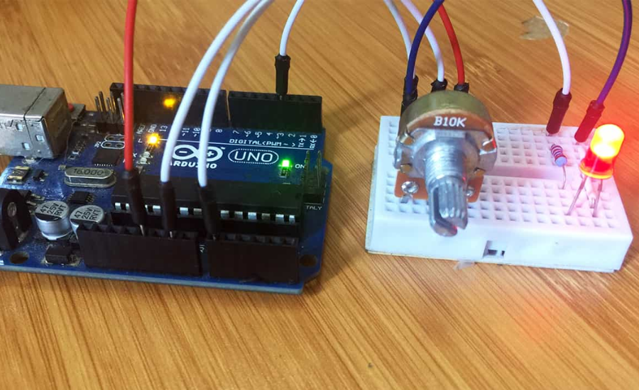
Pulse Width Modulation (PWM) is an effective method for adjusting the brightness of an LED by rapidly turning it on and off. The amount of time the LED stays on, compared to the total cycle time, is known as the duty cycle. This ratio has a direct impact on the perceived brightness of the LED. For example, a high duty cycle, such as 80%, results in the LED being on most of the time, which makes it appear brighter. Conversely, a low duty cycle, such as 20%, reduces the on-time, dimming the LED significantly. By controlling this on-off cycle, PWM provides an efficient way to manage brightness without the need for resistors.
Efficiency and Advantages of Using PWM for LED Control
One of the key benefits of using PWM to hook up LED to pie PWM dam is its efficiency. Unlike traditional methods where resistors are used to limit current and reduce brightness, PWM ensures the LED receives full power during the “on” phases. This means there is no wasted energy, as the LED is either fully powered or completely off. The use of PWM also results in smoother transitions when adjusting brightness, allowing for finer control and greater precision. These advantages make PWM a preferred method in a variety of applications where efficient energy use and fine control over brightness are important.
Understanding the Impact of Duty Cycle on LED Brightness
The duty cycle plays a crucial role in determining the amount of light an LED emits. A 100% duty cycle means the LED remains fully on, providing maximum brightness. On the other hand, a 0% duty cycle turns the LED off entirely. The brightness of the LED is directly proportional to the duty cycle percentage, so a 50% duty cycle would result in the LED being on half of the time, producing a medium brightness. By adjusting the duty cycle, you can easily control the intensity of the LED’s light output, making PWM an excellent tool for applications that require variable brightness levels.
Understanding Piezoelectric Devices and Their Functionality
Piezoelectric devices are specialised components that either generate an electrical charge when subjected to mechanical stress or produce mechanical vibrations when exposed to an electric field. These properties make them highly useful in various applications, such as in buzzers. In a piezoelectric buzzer, an alternating voltage, such as a Pulse Width Modulation (PWM) signal, causes the piezoelectric material to vibrate, thereby generating sound. The frequency and characteristics of the sound are determined by the properties of the applied PWM signal, making piezoelectric devices essential in audio and feedback systems.
Enhancing Sound Control with Hook Up LED to Pie PWM Dam
When you hook up LED to pie PWM dam, you can effectively control piezoelectric buzzers to produce different tones and frequencies, depending on the specifics of the PWM signal. The duty cycle and frequency of the PWM signal play a critical role in shaping the sound output. A higher duty cycle and frequency can generate more pronounced and varied tones, while a lower duty cycle will produce quieter and softer sounds. This capability makes piezoelectric buzzers particularly adaptable, allowing them to function as alarms, notifications, or feedback devices within electronic circuits. By adjusting these parameters, the versatility of piezoelectric buzzers expands, enabling their use in a wide range of applications.
How PWM Frequency Affects Piezoelectric Sound Quality
The performance of a piezoelectric buzzer is largely influenced by the frequency of the PWM signal it receives. When the frequency rises, the sound pitch from the buzzer also becomes higher. On the other hand, decreasing the frequency produces a lower pitch sound. In addition to frequency, the duty cycle of the PWM signal also affects the tone and volume of the sound. By fine-tuning both the frequency and duty cycle, you can control not only the pitch but also the overall quality and loudness of the sound emitted by the piezoelectric device. This precise control makes piezoelectric buzzers a highly efficient and flexible component in sound-based applications.
Setting Up the Circuit to Hook Up LED to Pie PWM Dam

To begin hooking up LED to pie PWM dam, the first step is to wire the LED properly. Start by connecting the anode (positive leg) of the LED to the PWM output pin on your microcontroller. Then, attach the cathode (negative leg) to the ground through a current-limiting resistor, typically around 220Ω, to prevent the LED from receiving too much current and burning out. This simple wiring setup is the foundation of controlling LED brightness using PWM signals.
Configuring the Microcontroller for PWM Control
Once the wiring is in place, the next task is to program the microcontroller to generate the correct PWM signal. In the microcontroller’s code, define the PWM frequency and duty cycle, which directly control the LED’s brightness. The frequency will determine how often the signal switches on and off, while the duty cycle dictates how long the LED stays on during each cycle. By adjusting the duty cycle in your code, you can fine-tune the LED’s brightness and create effects like fading or dimming.
Testing and Enhancing the Circuit for Higher Power LEDs
After programming the PWM signal, test the circuit by modifying the duty cycle and observing how the LED’s brightness changes. This simple test will demonstrate the effects of PWM on the LED. For LEDs requiring more power than the microcontroller can safely provide, you may need to incorporate a transistor into the circuit. The transistor acts as a switch, enabling the microcontroller to control the LED without overloading its output pins, allowing you to safely drive higher power LEDs with your PWM signal.
Simplifying PWM Programming for LEDs and Piezo Devices
Programming Pulse Width Modulation (PWM) for both LEDs and piezoelectric devices is relatively simple when using popular microcontroller platforms like Arduino IDE or Python on a Raspberry Pi. When working with LEDs, the code focuses on defining the appropriate PWM pin, adjusting the frequency, and varying the duty cycle to control the LED’s brightness. These steps make it easy to integrate PWM-controlled LEDs into your projects, whether for simple on/off states or more dynamic effects like fading or dimming.
Controlling Piezo Buzzers with PWM Signals
For piezoelectric buzzers, the approach involves modifying the frequency of the PWM signal to produce different tones. By adjusting the frequency, you can generate a range of pitches, which is ideal for creating sound effects or alarms in your project. This ability to change frequencies through PWM allows you to add audio feedback to your system, making it more interactive and responsive. Whether you’re designing a simple alert or a complex sound-based interaction, controlling piezo buzzers with PWM signals is a versatile solution.
Example Arduino Code for PWM Control of LED and Piezo Buzzer
Here’s a basic example of how to set up PWM on Arduino for both an LED and a piezo buzzer. The code defines the pin connected to the LED and the piezo buzzer, then configures these pins as outputs in the setup() function. In the loop() function, it adjusts the LED’s brightness to 50% using analogWrite(), while the piezo buzzer emits a 1kHz tone using the tone() function. This simple approach can be easily expanded for more complex projects involving both light and sound control through PWM signals.
Optimising PWM Frequency for Smooth LED Dimming
When setting up a circuit to hook up LED to pie PWM dam, fine-tuning the frequency is essential to achieve smooth and flicker-free LED dimming. If the frequency of the PWM signal is too low, it can cause noticeable flickering, which detracts from the overall user experience. To avoid this issue, a minimum frequency of 500 Hz is recommended to prevent flicker, although for most applications, a frequency of 1 kHz or higher is typically used to ensure a stable and smooth output. By adjusting the PWM frequency appropriately, you can ensure that your LED performs optimally, providing consistent brightness without the distraction of flickering.
Managing Current and Heat in High Brightness LED Applications
In circuits where LEDs are driven at higher brightness levels, especially over long durations, it’s important to carefully manage both current and heat. High-power LEDs can generate a significant amount of heat, which can degrade their performance or even cause damage if not properly managed. It’s crucial to choose the right current-limiting resistor to match the LED specifications, preventing excessive current from damaging the components. Additionally, when using LEDs at higher brightness levels, consider incorporating heat dissipation solutions such as heatsinks or proper ventilation to maintain safe operating temperatures and enhance the longevity of the components.
Ensuring Safe Operation in LED and Piezo Circuits
When working with LEDs and piezoelectric devices in a PWM-controlled circuit, ensuring the safe operation of all components is key. Both the LED and piezo buzzer, when used at high power, must be monitored for temperature and current levels to prevent overheating and overloading. By optimising the PWM frequency for the LED and properly managing the current and heat dissipation, you can enhance the performance and reliability of the circuit. With these precautions, you can hook up LED to pie PWM dam and enjoy stable, efficient operation for a variety of electronic projects.
How to Synchronise Light and Sound in Interactive Circuits
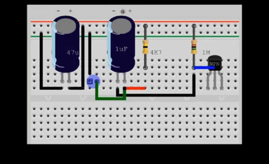
To integrate a piezoelectric buzzer into a PWM-controlled LED circuit, the first step is to connect the piezo device to a separate PWM pin on your microcontroller. This ensures that both the LED and the piezo buzzer can be controlled independently while still being part of the same circuit. Once the hardware is set up, you can use functions like analogWrite for the LED to adjust its brightness based on the PWM signal, and tone or noTone functions for the piezo buzzer to produce sound patterns. This setup allows for precise control over both the light output and the sound emitted by the buzzer, giving you flexibility in how the circuit responds to user inputs or events.
The combination of LED light and sound can enhance the interactivity of your project, offering dynamic feedback based on specific actions or conditions. For example, you could synchronise the flashing of the LED with different tones from the piezo buzzer to create an alarm system, a notification mechanism, or a visual and auditory indicator for any changes in the circuit. By manipulating the duty cycle of the PWM signal, you can control the brightness of the LED and the pitch or duration of the sound, allowing you to customise the behaviour of the circuit to suit various needs.
By hooking up the LED to the pie PWM dam signal, you open up many creative possibilities for designing circuits that offer both light and sound feedback. Whether you’re building a project for user interaction or creating an alert system, using PWM to control both visual and auditory outputs creates a cohesive and versatile solution. This method of integrating light and sound can greatly improve the functionality and appeal of electronic projects, making them more engaging and responsive to the user’s actions.
Using Transistors to Control High-Power LED Circuits
When working with high-power LEDs, a microcontroller’s PWM pin may not provide sufficient current to drive the LED. In these cases, a transistor can be used as a switch to control the current supplied from an external power source. The PWM signal from the microcontroller is used to control the transistor, which then adjusts the current that flows to the LED. This approach ensures that the LED receives the necessary power without overloading the microcontroller’s capabilities.
To ensure proper functionality and longevity of your components, it is essential to select the right type of transistor for your circuit. The transistor must be able to handle the current and voltage required by the LED. Depending on the power demands of your project, you may choose between an NPN transistor or a MOSFET, both of which have their unique characteristics and benefits. NPN transistors are typically used for lower power applications, while MOSFETs are better suited for higher power and more efficient switching.
By integrating a suitable transistor into the circuit, you can efficiently manage the power requirements of high-power LEDs while still using the microcontroller’s PWM pin for precise control. This setup allows the microcontroller to maintain control over the LED’s brightness or flashing patterns while ensuring that the necessary power is delivered to the LED. This method of using a transistor as a switch ensures the circuit operates efficiently and prevents damage to your microcontroller from excessive current draw.
Applications of PWM in LED and Piezo Devices for Enhanced User Interaction
The integration of Pulse Width Modulation (PWM) with LED and piezoelectric devices offers diverse applications across various fields. PWM’s ability to precisely control the brightness of LEDs and the frequency of piezo buzzers makes it a valuable tool for enhancing user experience in electronics. By adjusting the duty cycle, PWM enables fine-tuned regulation of both light intensity and sound, allowing for more responsive and interactive systems. This flexibility is particularly advantageous in user interfaces, where seamless visual and auditory feedback is essential for functionality.
In everyday applications, the combination of LEDs and piezo devices controlled by PWM can be seen in smart lighting systems, where LEDs adjust their brightness according to the surrounding environment or user preferences. Likewise, piezo buzzers can emit varying sound frequencies, adding auditory feedback to enhance user interaction. For instance, in a robotic feedback system, the synchronised operation of LEDs and buzzers provides both visual and auditory cues, improving communication between the device and the user. These systems rely on the accuracy and efficiency that PWM offers in managing both light and sound output.
This technology also finds its place in creative fields, such as musical instruments or alarms, where the dynamic interplay of light and sound is crucial. LED lights may be used to display different colours or brightness levels, while piezo buzzers generate tones that change in pitch and intensity. The integration of both elements, controlled via PWM, creates an engaging experience by providing visual and auditory effects that can be customised to suit the needs of the application.
Advantages of Using PWM for LED and Piezo Control in Electronic Projects
Using PWM to control LED and piezoelectric devices presents several key benefits over conventional methods. One of the main advantages is its energy efficiency, as power is regulated by switching the signal on and off rapidly, instead of reducing voltage. This method ensures minimal energy loss, making it a more effective option for various applications. Additionally, it allows for fine-tuned control, enabling smooth and gradual dimming of LEDs and precise modulation of sound from piezoelectric buzzers or speakers. This versatility makes it an ideal choice for projects requiring adjustable light levels and sound output.
Another advantage of utilising PWM for these components is its cost-effectiveness. Setting up a PWM-controlled circuit is relatively inexpensive due to the simplicity of the components involved. Basic elements like microcontrollers, resistors, and transistors are sufficient to create a functional system, making it an accessible solution for those working on personal or low-budget projects. This affordability is particularly beneficial in scenarios where multiple devices need to be controlled, such as in home automation, lighting systems, or other DIY electronics.
The flexibility of PWM circuits further enhances their appeal. They can be easily adapted to a variety of applications, ranging from hobbyist projects to more complex systems, with minimal changes to the basic setup. Whether you’re creating an interactive display, a sound-producing device, or a custom lighting solution, the ability to control both LED brightness and piezoelectric sound output makes this method highly versatile. It enables developers to experiment with a range of outputs while keeping costs and complexity low, offering a practical solution for many types of electronic designs.
Troubleshooting Common Issues in LED and Piezoelectric PWM Circuits

When working with circuits involving the connection of LEDs and piezoelectric devices to a PWM signal, several challenges may arise. One common issue is flickering LEDs, which can occur if the frequency is set too low or if there are unstable power connections. Similarly, piezoelectric devices might produce inconsistent sound or noise if the signal’s frequency is not properly calibrated or if there are faults in the wiring. Ensuring stable connections and verifying that the components are receiving the correct signals are crucial to achieving consistent performance in these setups.
To address flickering in LEDs or irregular sounds from piezo devices, adjustments can be made to the frequency of the PWM signal. A higher frequency can help reduce noticeable flicker in LEDs, while adjusting the signal for piezoelectric components can eliminate unwanted noises. It’s also essential to check that all connections are secure, as loose wires or faulty contacts can disrupt the performance of both the LED and piezo buzzer. Additionally, ensuring that the power supply is consistent and capable of handling the load can prevent fluctuations that might lead to erratic behaviour.
Another important aspect to monitor is the proper sizing of the current-limiting resistor. An incorrectly chosen resistor can either prevent the LED from receiving sufficient current or allow too much current, which could lead to overheating or damage. Therefore, selecting the right resistor for your specific LED and piezoelectric component is vital. Regular checks and maintenance of the circuit components will help maintain a reliable and stable connection, ensuring the smooth operation of the hook up LED to pie PWM dam system.
Conclusion
In conclusion, using Pulse Width Modulation (PWM) to control LEDs and piezoelectric devices offers a versatile method for regulating brightness and sound output. By adjusting the duty cycle of the PWM signal, you can easily control the intensity of the LED or the pitch and volume of the sound produced by a piezoelectric device. This technology is not only efficient but also widely applicable in various electronics projects, from lighting systems to sound devices. Proper component selection and management of power and heat are essential for ensuring reliable and effective operation.
FAQs
Q1. What is Pulse Width Modulation (PWM)?
A. PWM is a method used to regulate the power delivered to an electrical load by rapidly switching the power on and off. The proportion of time the signal is active in each cycle is called the duty cycle, and adjusting this allows for controlling the power output to components like LEDs and motors.
Q2. How does PWM affect an LED’s brightness?
A. PWM controls LED brightness by adjusting the duty cycle. A higher duty cycle means the LED stays on longer, making it brighter. A lower duty cycle means the LED stays off more, making it dimmer.
Q3. What role does a piezoelectric device play in a PWM circuit?
A. Piezoelectric devices, such as buzzers, respond to the PWM signal by vibrating and producing sound. By adjusting the PWM frequency and duty cycle, you can control the pitch and volume of the sound.
Q4. What components are needed to hook up an LED to a pie PWM dam?
A. You will need an LED, a current-limiting resistor, a microcontroller (e.g., Arduino or Raspberry Pi), and optionally, a piezoelectric device for sound feedback. If driving higher power LEDs, a transistor might be necessary to safely handle the power.
Q5. How can I control the brightness of an LED using PWM?
A. Brightness is controlled by adjusting the duty cycle of the PWM signal. A higher duty cycle (e.g., 80%) will result in a brighter LED, while a lower duty cycle (e.g., 20%) will dim the LED.
Stay engaged to receive the most recent updates and important alerts: Gossips

